
| Product Overview | ||||
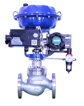
| The BSW-60 valve position transmitter converts the opening position of valves and other equipment into a 4–20 mA DC current signal for use by other monitoring devices. Manufactured with imported components, the product features a simple and reliable design, high conversion accuracy, and a long service life. | ||||
| Important Notes | ||||
|
||||
| ● Please handle with care during transportation, installation, and use. Excessive vibration and impact may damage the product. | ||||
| ● Do not use the product beyond the limits specified in its technical specifications. | ||||
| ● Do not store the product in environments with high temperatures or high humidity for extended periods. When in use, keep the housing securely closed to prevent rainwater from entering the product. | ||||
| Warranty Period | ||||
| The product warranty period is as specified on the purchase order. |
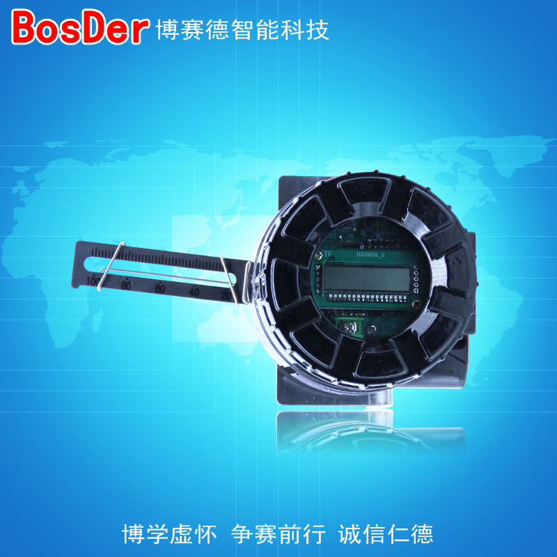
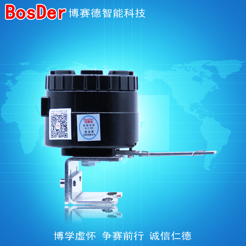
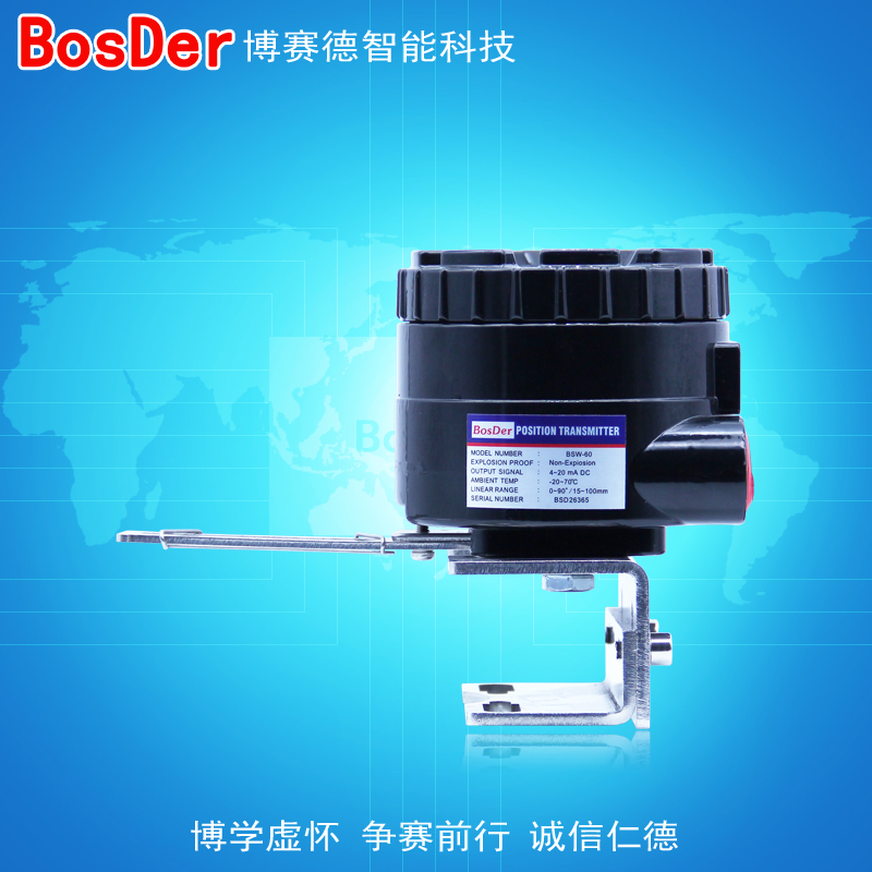
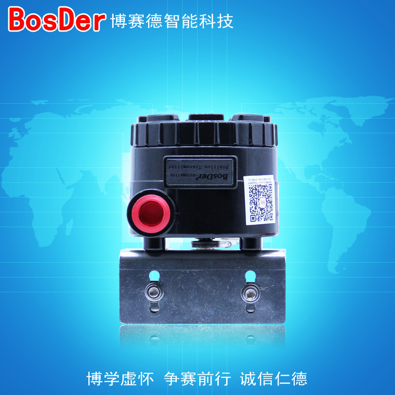
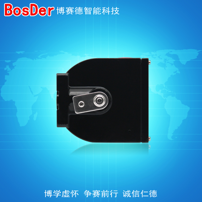
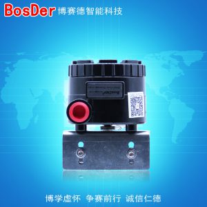

Valve Position Transmitter
BSW-60 Valve Position Transmitter
Specifications and Performance
| Technical Specifications | |||||||||||||||||||||||||||||||||||||||||||||||||||
|
|||||||||||||||||||||||||||||||||||||||||||||||||||
Installation and Commissioning
| Installation and Commissioning |
| Mechanical Connection |
| I. Installing the Feedback Rod |
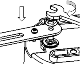 1. Slide the feedback rod onto the shaft at the bottom of the transmitter, paying attention to the direction of the shaft. 1. Slide the feedback rod onto the shaft at the bottom of the transmitter, paying attention to the direction of the shaft.
2. Use a 10mm open-end wrench to tighten the lock. |
| II. Installation on a linear actuator |
| Attach the universal mounting plate to the transmitter. |
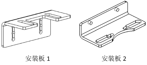 |
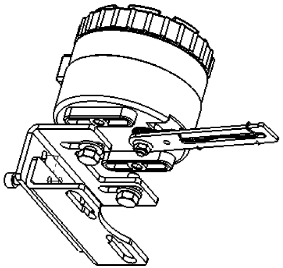 1. Use two M6 hex socket screws to secure mounting plates 1 and 2 together. Once mounted on the actuator, adjust the height as needed before tightening the screws. 1. Use two M6 hex socket screws to secure mounting plates 1 and 2 together. Once mounted on the actuator, adjust the height as needed before tightening the screws.
2. Secure the mounting plate to the transmitter body using two M8 screws, but do not tighten the screws yet. |
| Installed on a linear actuator |
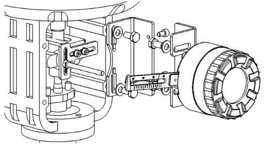 |
| Select screws of the appropriate size based on the mounting hole dimensions on the actuator to install the transmitter onto the actuator. Once the vertical alignment has been adjusted, tighten the mounting screws. |
| III. Mounting the Transmitter on the Actuator |
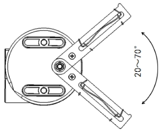 1. Fully open the actuator and observe the swing angle of the transmitter’s feedback lever. Adjust the swing angle by changing the position of the transmitter relative to mounting plate 1 so that the swing angle falls within the range of 20–70°. (The swing angle increases as the transmitter moves closer to the actuator.) 1. Fully open the actuator and observe the swing angle of the transmitter’s feedback lever. Adjust the swing angle by changing the position of the transmitter relative to mounting plate 1 so that the swing angle falls within the range of 20–70°. (The swing angle increases as the transmitter moves closer to the actuator.)
2. Adjust the actuator opening to the 50% position, and adjust the vertical position of mounting plate 2 so that the feedback plate is level. 3. Tighten the mounting screws to securely attach the mounting plate to the actuator. 4. Move the transmitter horizontally so that the notches on the feedback rod align with the markings on the feedback plate. 5. Tighten the mounting screws between Mounting Plate 1 and the transmitter to complete the installation. |
| IV. Installation on an angular-travel actuator |
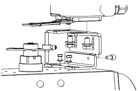 |
| 1. Secure mounting plate 2 to the actuator with two M5 screws, and tighten the screws.
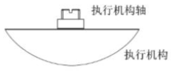
2. Secure the angular travel stop rod to the actuator and adjust it to the proper height. 3. Secure the transmitter, with the feedback rod attached, to the quarter-turn mounting plate using two M8 screws, and insert the feedback rod into the center slot of the feedback plate. 4. Carefully inspect the shift lever to ensure that it slides reliably within the slot of the feedback rod without contacting the bottom of the transmitter or the actuator. If the transmitter feedback plate’s swing angle exceeds 90°, loosen the bolts connecting the transmitter to mounting plate 1 to move the transmitter farther away from the center of the actuator; if the swing angle is too small, do the opposite. 5. The height of the actuator shaft protrusion varies; this can be adjusted by changing the distance between mounting plates 1 and 2 or the height of the stop bar. 6. Tighten all mounting screws. |
 |
| Electrical Connections | ||
| Important Notes | ||
|
||
| Feedback Signal Connections | ||
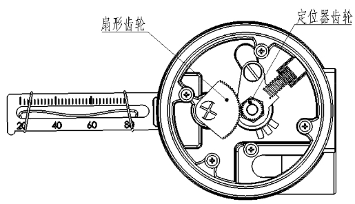
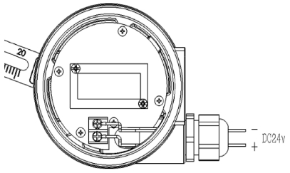 The terminals on the transmitter circuit board are not polarized; connect the two wires from the feedback loop to the terminals respectively. The terminals on the transmitter circuit board are not polarized; connect the two wires from the feedback loop to the terminals respectively. |
||
| Feedback Signal Adjustment | ||
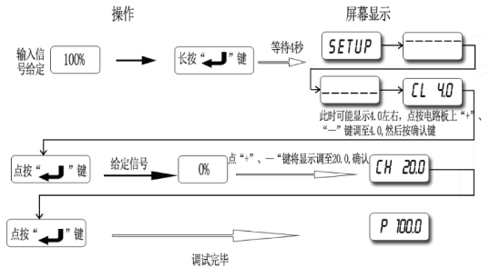
| 1. First, connect the feedback signal circuit.
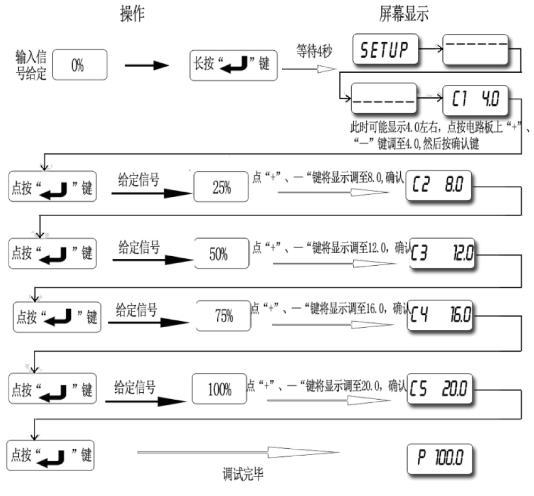
2. Next, adjust the feedback signal by following the steps below. (1) If the actuator is an incremental valve (4–8–12–16–20 mA), set the “SW” switch on the right side of the transmitter’s display to “5.” |
||
 |
||
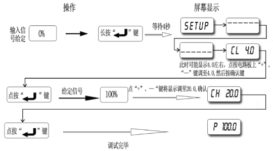
| (2) If the actuator is a on/off valve (4–20 mA), set the “SW” switch on the right side of the transmitter display to “2.” | ||
 |
||
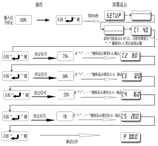
| (3) When the output signal needs to be the opposite of the input signal, and the actuator is an incremental valve (4–8–12–16–20 mA), set the “SW” switch on the right side of the transmitter display to “5.” | ||
 |
||
| (4) When the output signal needs to be the opposite of the input signal, and the actuator is a on/off valve (4–20 mA), set the “SW” switch on the right side of the transmitter’s display to “2.” | ||
 |
| Common Troubleshooting | |||||||
|
|||||||
 |
|||||||
 |
|||||||
 |
|||||||
 |
Ordering Information
| Order Code | |||
| BSW-60 □□ | |||
|
|||
| Ordering Information | |||
| 1. Name, Model Number | |||
| 2. Attachments | |||
| Providing detailed process data and automation documentation will help ensure that you order a product that is more suitable and meets your needs. |
Related products
-
 Self-Actuated Ball Valve
BSW-510 Position Transponder