
| Product Overview | ||||
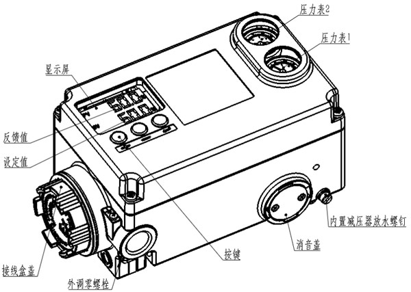
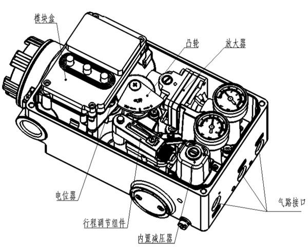
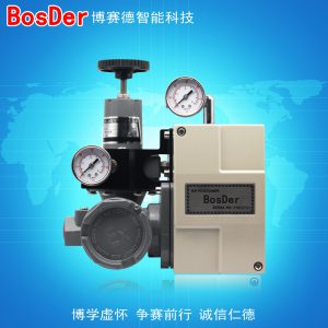
| The BSW-100 electric valve positioner is a device that receives a 4–20 mA DC current signal for control and operates via a pneumatic actuator. 行器来精确调整阀门开度的装置。定位器自带空气过滤减压器,显示现场阀位开度 (百分比)及输出反馈信号(4~20mA),直接将 5~10kgf/cm2 压力范围的压缩空气接至定位器“SUP”输入接口即可。 |
||||
|
||||
| Important Notes | ||||
|
||||
| ● Please handle with care during transportation, installation, and use. Excessive vibration and impact may damage the product. | ||||
| ● Do not use the product beyond the limits specified in its technical specifications. | ||||
| ● Do not store the product in environments with high temperatures or high humidity for extended periods. Be sure to keep the lid tightly closed during use to prevent rainwater from entering the product. | ||||
| Warranty Period | ||||
| The product warranty period is based on the date of manufacture and is valid for 1 year. |
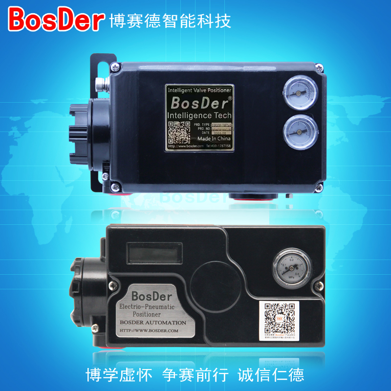
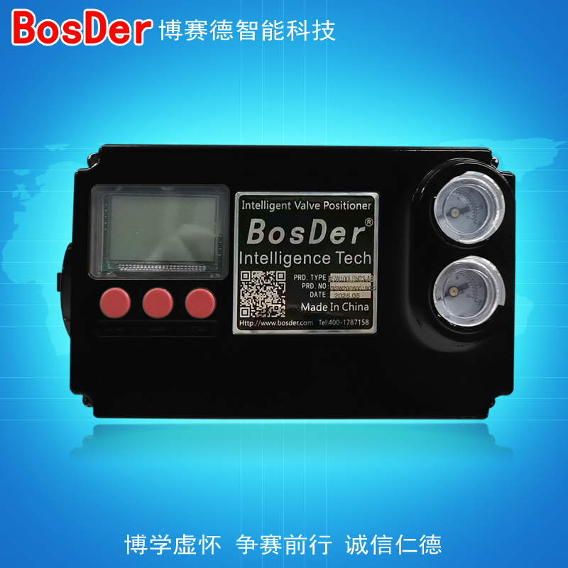
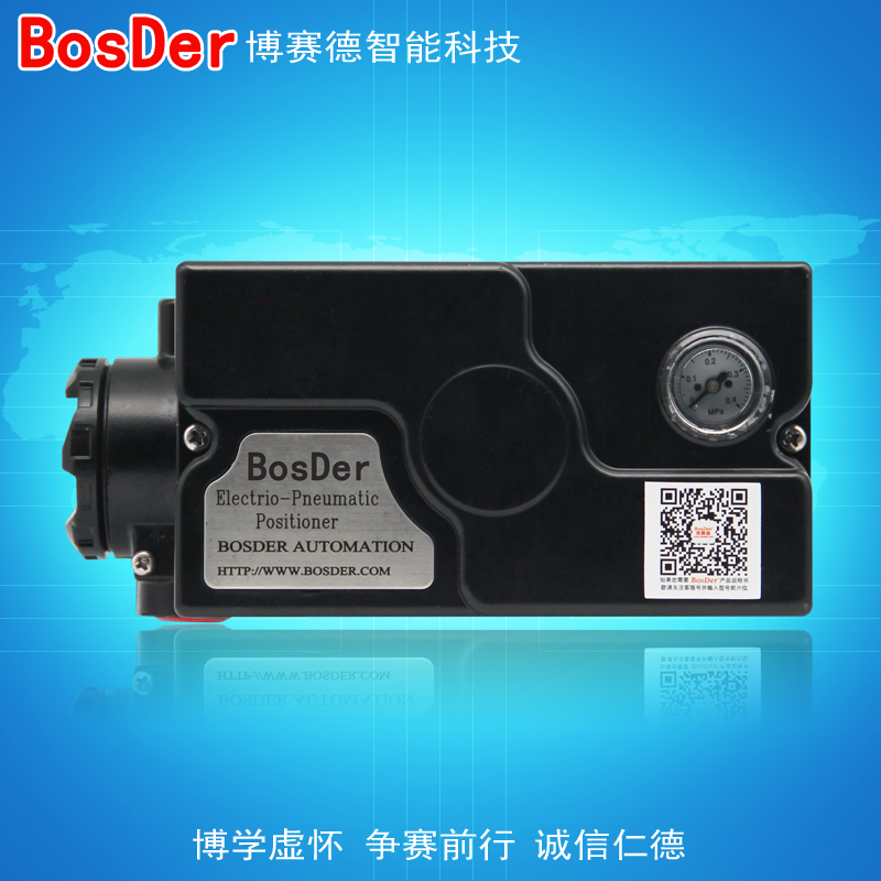
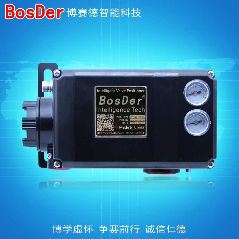
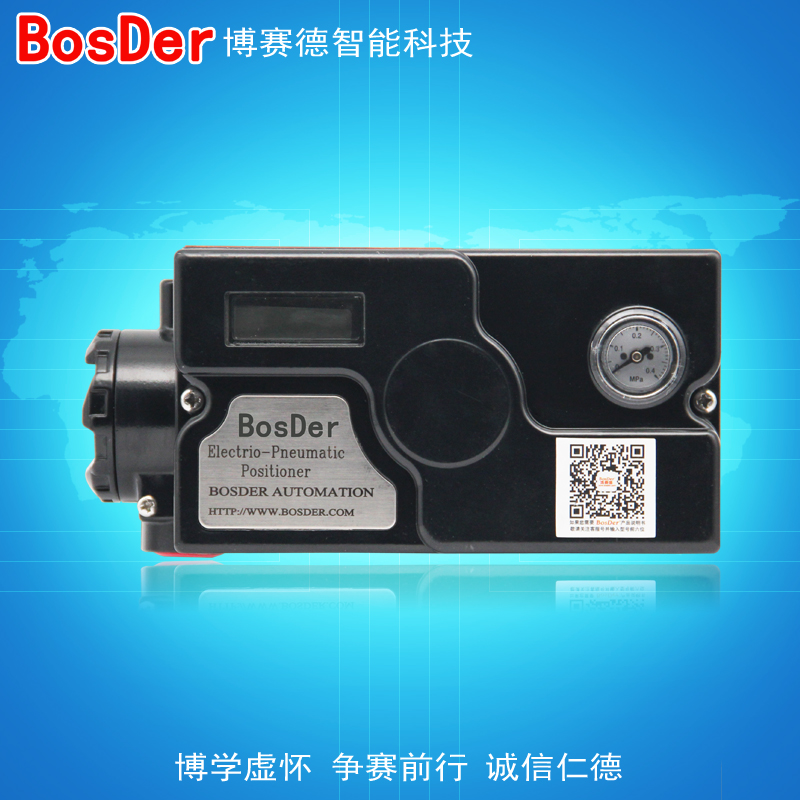
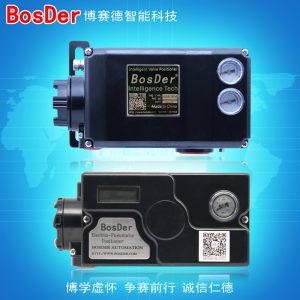

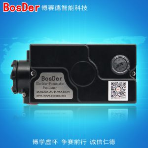
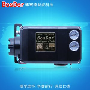
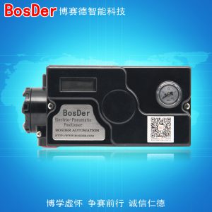
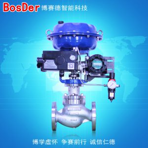
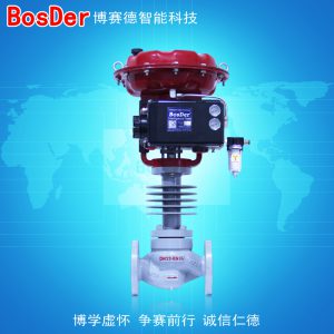
Standard Valve Positioner Series
BSW-100 Series Electric Valve Positioners
Product Specifications
| Technical Specifications |
| Table 1 |
| Project | BSW-100L | BSW-100R | |||
| Single-action | Dual-action | Single-action | Dual-action | ||
| Input Signal | 4–20 mA DC | ||||
| Impedance | 250±15Ω (non-feedback model) | ||||
| Supply Pressure | 1.4~7.0kgf/cm2(20~100psi) | ||||
| Itinerary | 10–150 mm | 0–90° | |||
| Air Supply Connection Size | PT (NPT) 1/4 | ||||
| Pressure Gauge Connection Sizes | PT (NPT) 1/8 | ||||
| Power Connector Dimensions | PF 1/2 (G 1/2) | ||||
| Protection Rating | IP66 | ||||
| Ambient Temperature | Operating Temperature | Standard Model: -20 to 70°C
Low-Temperature Model: -40 to 70°C (no display below -20°C) |
|||
| Explosion-proof temperature | -20 to 60°C | ||||
| Linear | ±1.01 TP3T F.S. | ||||
| Lag | 1.01 TP3T F.S. | ||||
| Sensitivity | ±0.21 TP3T F.S. | ±0.51 TP3TF.S | ±0.21 TP3T F.S. | ±0.51 TP3TF.S | |
| Repeatability | ±0.51 TP3T F.S. | ||||
| Air Consumption | 3 LPM (Sup = 1.4 kgf/cm², 20 psi) | ||||
| Traffic | 80 LPM (Sup = 1.4 kgf/cm², 20 psi) | ||||
| Material | Die-cast aluminum | ||||
| Weight | 2.5 kg | ||||
| Models with digit display/feedback functionality | |||||
| Input Signal | 4–20 mA DC (two-wire) | ||||
| Input Load Voltage | MAX 15V | ||||
| Feedback Signal | 4–20 mA DC (two-wire) | ||||
| Feedback Signal Power Supply | DC 24V ±15 % | ||||
Installation and Commissioning
| Installation | |||
| Mechanical Connection | |||
| Important Notes | |||
|
|||
| Installed on a linear actuator | |||
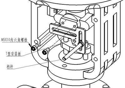 Installation of Accessories Installation of Accessories
1. Remove the locator and installation accessories. 2. Use two M5 hex socket screws to secure the “T-plate” to the valve pushrod as shown in the figure on the left. 3.档杆用其自带的两颗螺母固定于 T 型板槽内。 |
|||
| Installation of the Locator
1. Place the positioner, along with its mounting plate, on the valve. Align the keyway on the mounting plate with the two bolt holes on the valve mounting bracket, and secure it with two M10 hex head bolts. Do not tighten the bolts yet; wait until the positioner is installed and adjusted to the proper height before tightening them. 2. Place the gearshift lever in the groove of the positioner’s feedback rod; the clearance between the gearshift lever and the bottom of the positioner must not be less than 5 mm. 3. Adjust the relative position of the mounting plate and the stop rod according to the actuator's stroke length so that the vertical distance h between the positioner's feedback shaft and the stop rod is approximately equal to half the actuator's stroke, then tighten the nut. |
|||
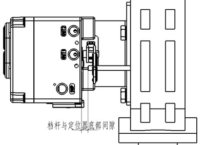 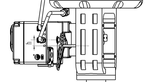 |
|||
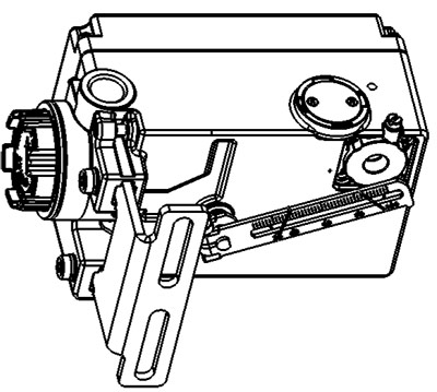 Note: To improve positioning accuracy, in linear actuators Note: To improve positioning accuracy, in linear actuatorsWhen installing, refer to the table below for the left or right position of the shift lever within the feedback lever slot. (You can adjust their relative positions by moving the “T-shaped plate” left or right and by reversing the mounting plate.) |
| Actuator Stroke | Position of the shift lever within the shift lever slot |
| 25 or less | 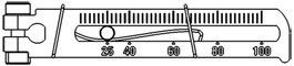 档杆置于25刻度左右 档杆置于25刻度左右 |
| 25~100 | 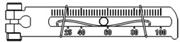 档杆置于25~100刻度之间 档杆置于25~100刻度之间 |
| 100 and 100 or more | 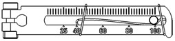 档杆置于100刻度左右 档杆置于100刻度左右 |
| Installed on an angular-travel actuator |
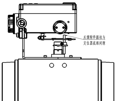
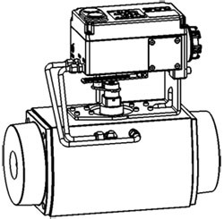
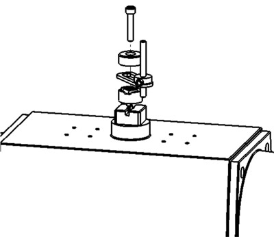 1. Secure the mounting bracket to the cylinder. 1. Secure the mounting bracket to the cylinder.2. Place the positioner with the mounting plate attached onto the cylinder and install it as shown in the diagram, placing the stop pin into the slot on the feedback rod. 3.调整档杆高度,与定位器底部保持 5mm 以上距离,并调整固定档杆的“8 字”型板水平伸出长度,使档杆靠近反馈杆槽中间位置。 4. Tighten all mounting screws. |
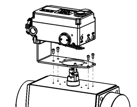  |
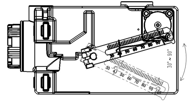 To ensure proper operation, the feedback lever's swing angle must be between 30° and 90° when the valve is fully open. To ensure proper operation, the feedback lever's swing angle must be between 30° and 90° when the valve is fully open. |
| Electrical Connections | |||||||||
| Important Notes | |||||||||
| Note | The locator has a rated operating voltage of 24 V and a maximum operating voltage of 26 V. Prolonged operation at voltages exceeding the rated voltage may result in unforeseen issues. | ||||||||
| The status of the feedback signal is uncertain when there is no signal from the positioner. Do not use the feedback signal as a critical interlock signal. | |||||||||
| Wiring Methods for Signal and Feedback Lines | |||||||||
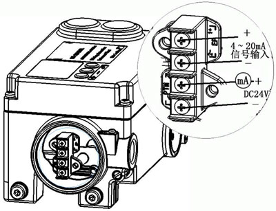 Signal Line Connections Signal Line Connections1. Connect the “+” terminal of the EP to the positive terminal of the PLC (DCS) 4–20 mA output signal, and connect the “–” terminal of the EP to the negative terminal of the output signal. 2. Suitable for use with 0.5–1.5 mm² cables. Feedback Signal Line Connection 1. PTM: Connect the two terminals to the positive and negative terminals of the feedback signal circuit, respectively; there is no polarity distinction between the two terminals. 2. Suitable for use with 0.5–1.5 mm² cables. |
|||||||||
| Piping | |||||||||
| Note | Make sure the piping is properly connected before turning on the compressed air supply to prevent accidents. | ||||||||
| When the compressed air supply is turned on, the regulating valve may activate; ensure the safety of the work area and piping before turning on the air supply. | |||||||||
| A source of compressed air that has been dried, degreased, and dust-removed must be used. | |||||||||
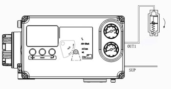
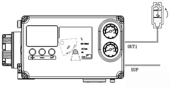
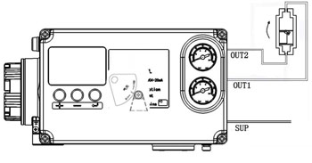
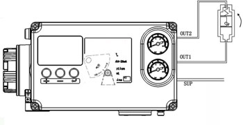
| Note: The positioner is set to “air-to-open” (reverse-acting) by default at the factory. When installed on an air-to-open valve, connect the air line directly; when installed on an air-to-close valve, flip the cam as shown in the "Air-to-Close Valve" column of Table 3.
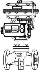
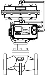
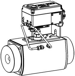
Piping Connections Between Positioners and Actuators |
|||||||||
| Actuator Piping Connections | |||||||||
| Table 2 | |||||||||
|
|||||||||
| Determine the cam profile based on the actuator's operating mode | |||||||||
| After the positioner is mounted on the actuator, if the actuator is single-acting, you can determine whether to use the “air-to-close” or “air-to-open” cam surface based on the rotation direction of the positioner’s feedback rod when a signal is output from the “OUT1” port. For double-acting actuators, the cam surface can also be determined based on the rotation direction of the positioner’s feedback rod when a signal is output from “OUT1.” | |||||||||
| Table 3 | |||||||||
|
|||||||||
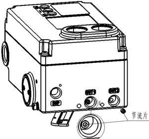 When adjusting the orifice for the assembly of small-displacement actuators, to prevent oscillation, a throttling plate can be installed at the positioner outlet, or a throttling fitting can be used. These are not included by default at the factory; if throttling is required, please specify this when placing your order. When adjusting the orifice for the assembly of small-displacement actuators, to prevent oscillation, a throttling plate can be installed at the positioner outlet, or a throttling fitting can be used. These are not included by default at the factory; if throttling is required, please specify this when placing your order. |
|||||||||
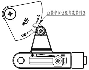 If you need to flip the cam, simply unscrew the “locking bolt,” install the cam upside down on the shaft, tighten the “locking bolt” again, and swap the “OUT1” and “OUT2” air lines. After reinstalling the cam, when the actuator is open to approximately 50%, the center mark on the cam should align with the roller. If you need to flip the cam, simply unscrew the “locking bolt,” install the cam upside down on the shaft, tighten the “locking bolt” again, and swap the “OUT1” and “OUT2” air lines. After reinstalling the cam, when the actuator is open to approximately 50%, the center mark on the cam should align with the roller. |
|||||||||
| Debugging |
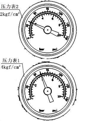
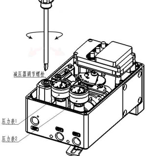 Adjust the pressure regulator Adjust the pressure regulatorOpen the locator cover and use a flathead screwdriver to adjust the pressure reducer's adjustment screw, setting the pressure on Pressure Gauge 1 to the actuator's nominal pressure. |
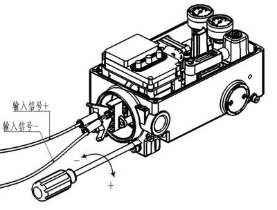 Zero Adjustment Zero Adjustment
1. Connect the signal input cable and apply a 4 mA (0%) signal. Use a flathead screwdriver to gently turn the zero adjustment screw; turning it clockwise in the direction shown in the figure increases the zero point, while turning it counterclockwise decreases it. 2. If the actuator is single-acting, turn the zero-adjustment screw clockwise until pressure builds up in pressure gauge 2 and the valve moves slightly. Then, turn the zero-adjustment screw in the opposite direction until the pressure in pressure gauge 2 returns to zero, and the valve returns to its starting position. 3. If the actuator is double-acting, turn the zero-adjustment screw clockwise until the pressure on Pressure Gauge 2 rises to the valve’s nominal pressure, then turn the zero-adjustment screw counterclockwise until the pointer on Pressure Gauge 2 points to half the valve’s nominal pressure. For example: If the actuator's operating pressure is 4 kgf/cm², adjust it as shown in the figure on the left. |
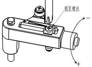 Itinerary Adjustments Itinerary Adjustments
With a 20 mA (100%) signal applied, check whether the actuator is fully open: 1. If the valve is fully open, reduce the input signal to 19 mA and check whether the valve actuates. If it does not actuate, this indicates that the stroke is too long. Use a Phillips screwdriver to loosen the locking screw on the stroke bracket, then turn the stroke adjustment knob 2 to 3 turns in the “-” direction. tighten the Phillips screw, apply a 4 mA signal, and readjust the zero point. Then apply signals of 20 mA and 19 mA in sequence until the valve opens fully at a 20 mA signal and moves when the signal is reduced to 19 mA. 2. If the valve does not fully open when a 20 mA signal is applied, use a Phillips screwdriver to loosen the locking screw on the travel bracket, then turn the travel adjustment knob 2 to 3 turns in the “+” direction, tighten the locking screw, readjust the zero point, and apply the 20 mA and 19 mA signals again until the valve opens fully when the 20 mA signal is applied and the valve begins to move when the signal is reduced to 19 mA. The stroke adjustment is now complete; replace the cover. |
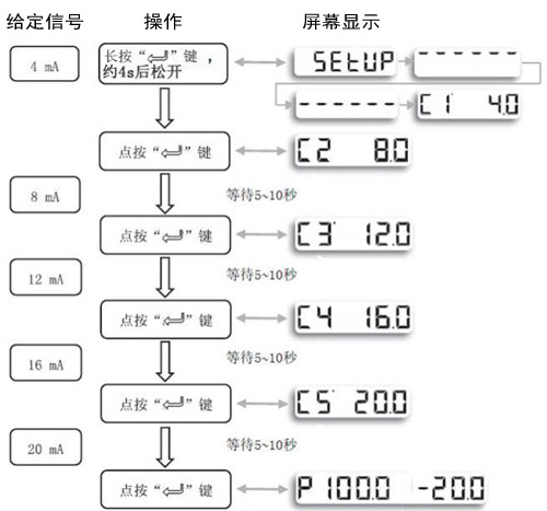
| Feedback Calibration |
| Connect the signal and feedback lines properly. 1.按如下步骤调试反馈信号。 |
 |
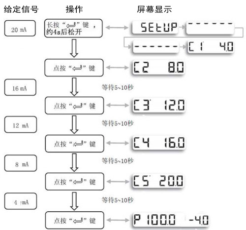
| 2.如需输入信号与反馈信号相反时,按下列步骤设定。 |
 |
| 显示屏为输入输出双显示。 |
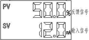  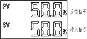 |
| Tap the “+” button to switch the display mode for the input signal. |
| Product Maintenance and Inspection |
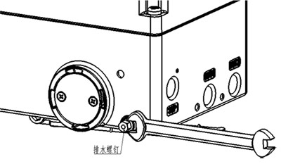 1. Regularly check the output pressure of the valve positioner’s air filter-regulator; do not arbitrarily increase or decrease the regulator’s output pressure. 1. Regularly check the output pressure of the valve positioner’s air filter-regulator; do not arbitrarily increase or decrease the regulator’s output pressure.
2. Drain the air filter regulator regularly to prevent moisture from inside the regulator from entering the positioner and causing it to malfunction. To drain the regulator, simply turn the drain screw counterclockwise two turns; after draining, tighten the screw. 3. During normal use, please keep the locator's housing closed to prevent water, moisture, dust, and other contaminants from entering the locator and causing malfunctions. |
| Common Troubleshooting | ||||||||||||
|
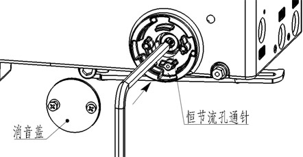
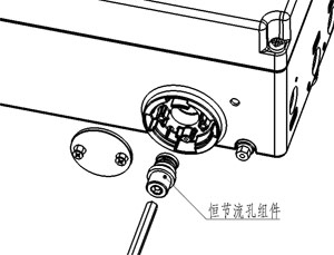
| Clear the constant-flow orifice |
| 1. Open the side muffler cover and use a hex wrench no larger than 5 mm or another tool to press the “cleaning pin” down several times to clear the “constant throttle hole.”
2. If the blockage cannot be cleared, shut off the air supply, use a 5mm hex wrench to unscrew the constant orifice assembly, then turn on the air supply to blow out the internal air passages of the positioner. Next, shut off the air supply, apply lubricant to the threads of the constant orifice assembly, and screw it back into its original position. Be careful not to lose the O-ring when reassembling. |
  |
| Warning: | |
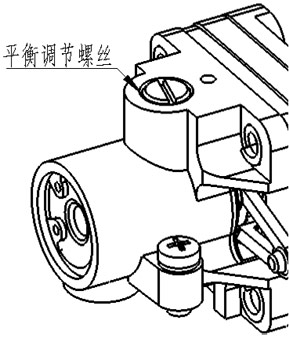 1. Do not adjust the amplifier's “balance adjustment screw.” |
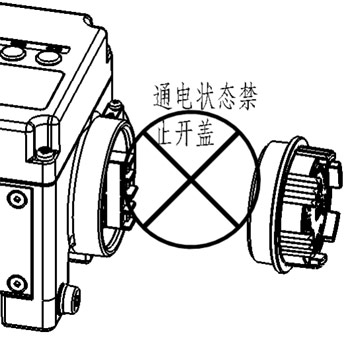 2. The junction box cover may only be opened after the power has been turned off. |
Ordering Information
| Ordering Information | ||||||||||||
| Order Code BSW-100 1 2 3– 4 5 For example: LDN-45 Linear-stroke, double-acting, non-explosion-proof, with digital display and pressure-reducing valve |
||||||||||||
|
||||||||||||
| If you have any special requirements, please contact the manufacturer. |
Related products
-
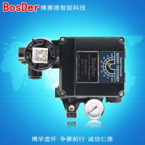 Standard Valve Positioner Series
BSD-5000 Valve Positioner
-
 Standard Valve Positioner Series
BSW-1000 Valve Positioner