| User Guidelines |
| Please read this manual carefully before installation and commissioning. |
| I. Safety Icons |
| To help you make the best use of this manual and to ensure your safety during the commissioning, operation, and maintenance of this instrument, please be aware of the meanings of the following symbols: |
| Symbol |
Slogans |
Commentary |
 |
Warning |
This warning indicates that if a certain operation or procedure is not performed properly, it may result in personal injury or a safety incident. Please strictly follow the guidelines and proceed with caution. |
 |
Note |
If an operation or procedure is not performed correctly, it may result in equipment malfunction or damage. Please strictly follow the guidelines. |
 |
Note |
If an operation or procedure is not performed properly, it may indirectly affect the operation of the equipment or trigger an unintended response in a part of the equipment. |
|
| II. Safety Precautions |
|
1. This equipment is designed to meet advanced safety requirements, has passed factory testing, and is safe and effective for operation upon shipment. |
| 2. This equipment complies with relevant regulations and standards. |
| 3. The manufacturer of this equipment reserves the right to modify the technical specifications without prior notice. |
| 4. The permitted storage, transport, and operating temperatures must be observed. |
| 5. The equipment must be wired in accordance with the wiring diagram. |
| 6. You must follow the instructions provided on the warning labels, nameplates, and wiring diagrams included with the equipment. |
| 7. Equipment intended for use in hazardous areas is marked accordingly on its nameplate. When operating equipment in hazardous areas, you must comply with relevant national regulations. You must follow the installation specifications, connection parameters, and safety instructions provided in this Ex explosion-proof documentation. |
|
| III. Scope of Application |
|
1. Any use other than those specified in this manual poses a safety hazard to personnel and the entire equipment system and is strictly prohibited. |
| 2. The manufacturer shall not be liable for any damage resulting from improper operation or use for purposes other than those specified. |
|
| IV. Installation and Commissioning Procedures |
|
1. This equipment may only be installed, connected, commissioned, and maintained by trained, authorized, and qualified professionals (such as electricians). All work must be performed in full compliance with the guidelines in the *User Manual*, relevant application standards, and legal and regulatory requirements, and the professionals must hold the appropriate certification (as required by the application conditions). |
| 2. Before installing this equipment, the installer must read the *User Manual*, understand its provisions, and comply with them. |
| 3. When installing this equipment, ensure that the power is turned off and that there are no external loads or stresses. |
| 4. Unless permitted by the User Manual, do not modify or repair the device. |
| 5. Repairs to this equipment may only be performed if explicit authorization has been granted and only original equipment parts are used. |
| 6. If welding operations are being performed near this equipment, do not use this equipment to ground the welding equipment. |
|
| Dimensions |
 |
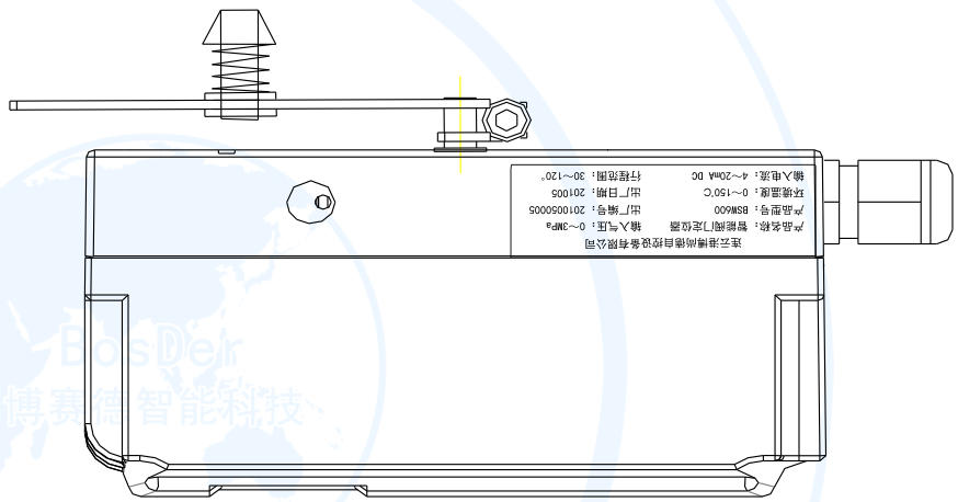
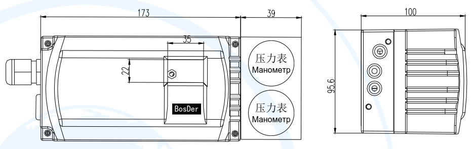 |
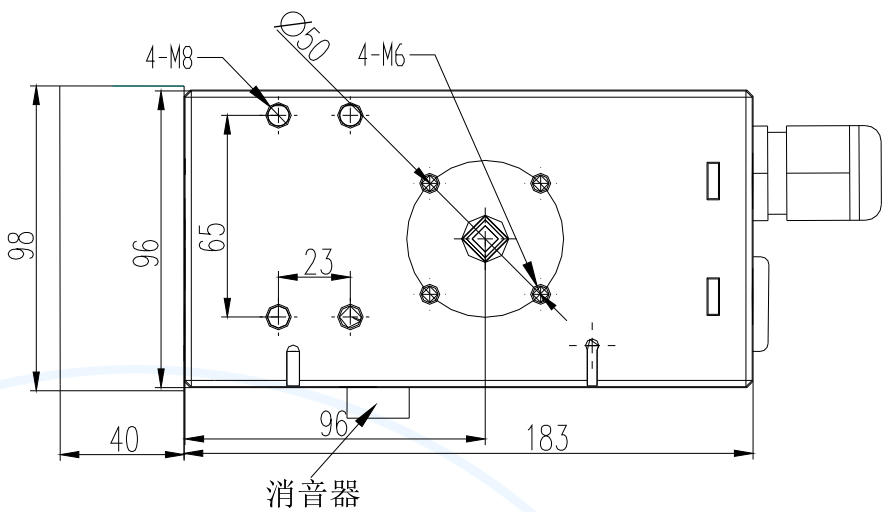
| BSW600 Smart Valve Positioner Dimensions Diagram |
| Linear-Travel Mounting Accessories |
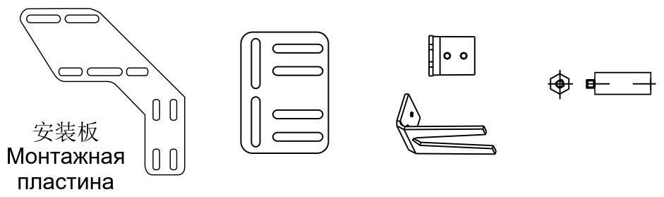 |
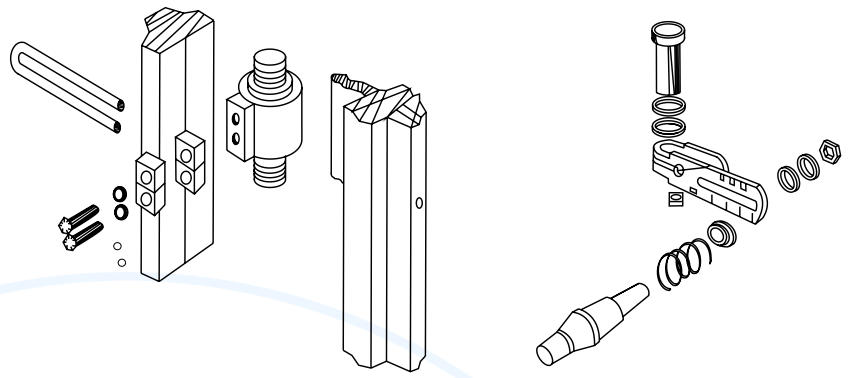 |
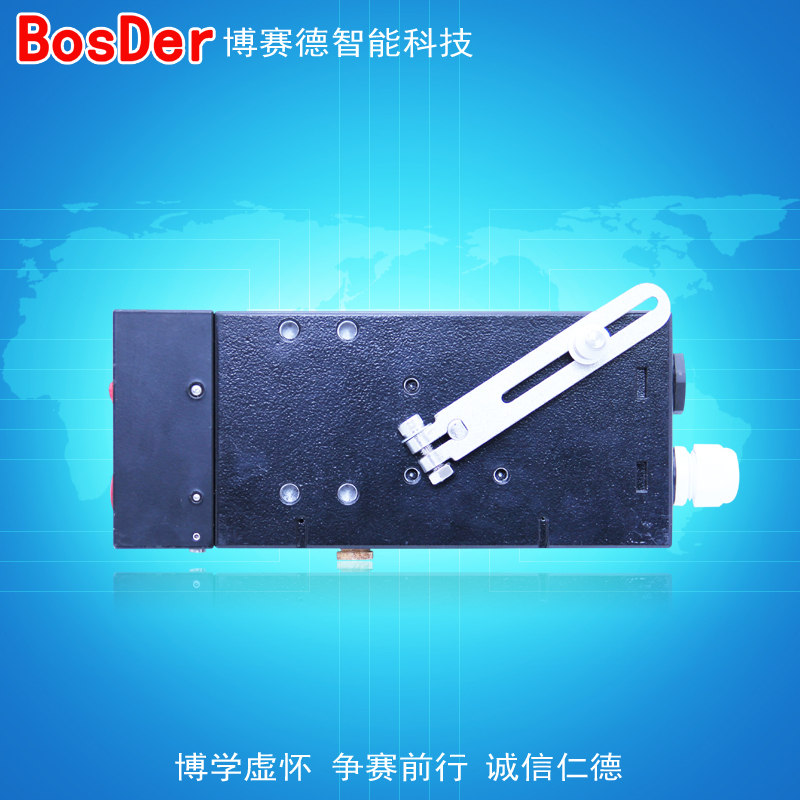
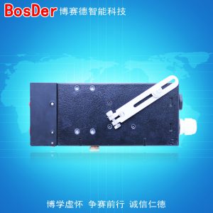
| The feedback rod is mounted on the positioner. |
 |
| Installation and Connection of Angular Travel Positioners |
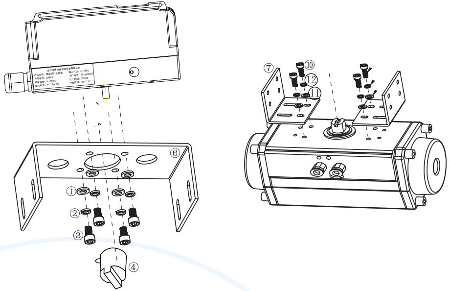 |
| The installation steps are as follows (see Figure 4.2.3 for the installation and connection of the angular travel positioner) |
| 1. Use the flat washer ①, spring washer ②, and hex head screw ③ to secure the upper bracket block ⑥ to the bottom of the positioning device. |
| 2. Slide the feedback rod ④ onto the positioner's drive shaft and secure it with a set screw. |
| 3. Use flat washers 12, spring washers 11, and hex head screws ⑩ to secure the two lower bracket blocks ⑦ to the actuator. |
4. First, screw the hex nut (9) into the base of the fork-shaped feedback rod (8), then attach the fork-shaped feedback
Screw rod ⑧ onto the actuator. |
| 5. Carefully place the positioner, with the mounting bracket attached, onto the actuator so that the cylindrical pin on the feedback rod ④ is correctly inserted into the slot of the fork-shaped feedback rod ⑧. Adjust the positioner’s mounting height, tighten the lock nut on the cylindrical pin of feedback rod ④, and secure the positioner to the actuator using the upper and lower mounting blocks, flat washers 15, spring washers 14, and hex screws 13. Adjust the rotation angle of the feedback rod to meet the requirements specified in Section 4.2.1. |
|
1. When installing a valve positioner, ensure that the mounting bracket does not block the positioner’s vent hole; |
| 2. The rotation angle of the feedback rod shall comply with the requirements specified in Section 4.2.1; |
| 3. When the linear-travel valve is open to 50%, the feedback rod is horizontal. |
|
| Air Line Connections |
| The air connections are located on the right side of the positioner. There are two types of air connections available: G1/4 and 1/4 NPT (please select the appropriate model when ordering). The specific type is marked on the housing, and users can choose the connection that best suits their piping configuration. |
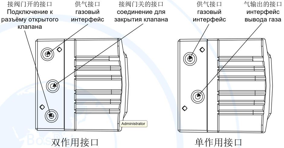 |
| Figure 4-7: Pneumatic Connection Diagram |
| Installation Instructions: |
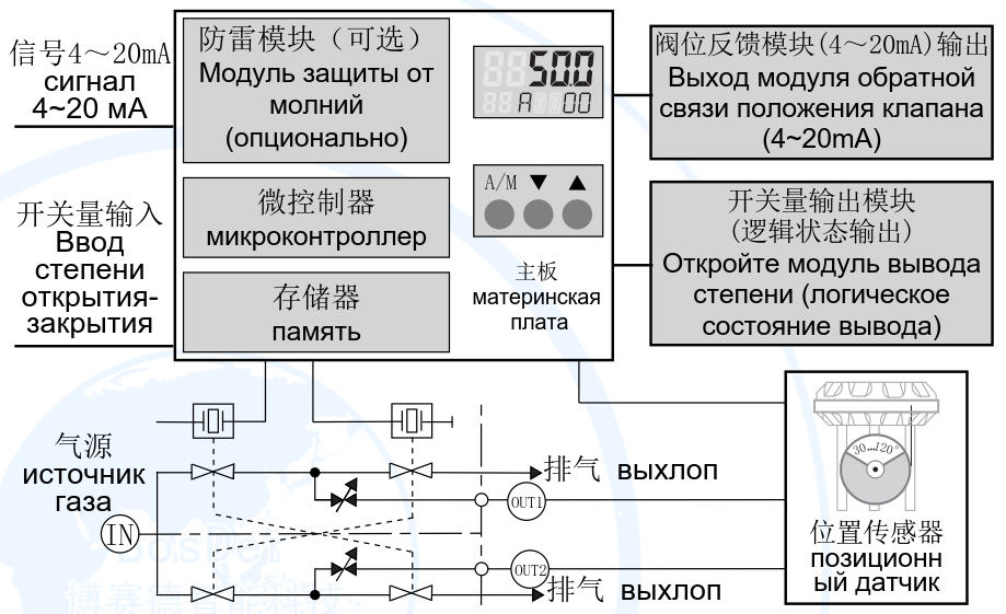
| Connect the outlet of the smart valve positioner to the inlet of the pneumatic actuator as shown in Figure 4-7. |
|
To prevent air leaks at the connections, use soapy water to check the airtightness of the joints. |
|
| Connect the IN port of the valve positioner to the air supply. The compressed air entering the positioner must be filtered and regulated by an air filter-regulator. |
| Air Supply Requirements: |
| The air supply pressure must be between 0.14 and 0.7 MPa; the specific value depends on the actuator; |
| The air supply must be clean and dry, and must be free of noticeable oil vapors, oil, and other liquids; |
| The air supply should be free of any noticeable corrosive gases, vapors, or solvents; |
| Maximum particle size and density in the air supply: Class 4; oil content: Class 4; |
| The dew point of the process gas supply must be at least 10 K lower than the minimum ambient temperature. |
| Electrical Connections |
| Electrical Connection Requirements |
| Electrical connections must be made strictly in accordance with the wiring diagrams, secured reliably, and must not be loose. |
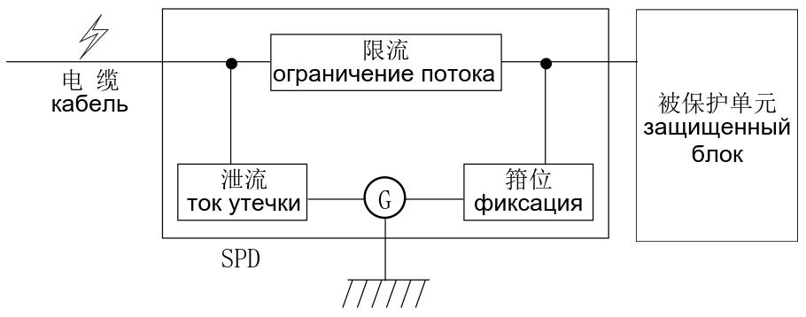
Intrinsically safe positioners must be used in conjunction with associated equipment or intrinsically safe devices that have already been certified as explosion-proof to form an intrinsically safe system before they can be used in explosive gas atmospheres. The system wiring must
You must follow the instructions in the user manuals for both the locator and its associated equipment/intrinsically safe devices; do not connect the terminals incorrectly. |
This product comes standard with a waterproof cable connector. The signal cable must have an outer diameter of at least 8 mm, and the connector cap must be securely tightened during installation to prevent a reduction in the product’s IP rating: If
Users who configure cable entry devices on their own must use cable entry devices or seals that are approved by a nationally authorized inspection agency, comply with the provisions of national standard GB/T 4208-2017, and have an enclosure protection rating of at least IP20; only such devices may be used in potentially explosive atmospheres. |
| There should be no gases at the installation site that could corrode the product's housing. |
| When installing, using, and maintaining this intrinsically safe positioner, you must strictly comply with both the product manual and the following standards: |
| GB 3836.13-2013 Explosive Atmospheres—Part 13: Repair, Maintenance, Restoration, and Modification of Equipment; |
| GB/T 3836.15-2017 Explosive Atmospheres—Part 15: Design, Selection, and Installation of Electrical Equipment; |
| GB/T 3836.16-2017 Explosive Atmospheres—Part 16: Inspection and Maintenance of Electrical Installations. |
| Intrinsically Safe Positioner Connection |
| Input Electrical Connections (as shown in Figure 10) |
| Type: |
Two-wire system |
| Input Signal: |
4–20 mA DC |
| Minimum operating current: |
3.8 mA DC |
| Input Impedance: |
325 Ω, 20 mA DC (without HART) |
| 375 Ω, 20 mA DC (HART type) |
| Intrinsic Safety Parameters (6+ to 7-): |
Ui = 28 V DC |
| Ii = 93 mA |
| Pi = 0.65 W |
| Ci = 18 nF |
| Li ≈ 0 |
| Safety Barrier Requirements: |
U0 ≤ 28 V DC |
| I0 ≤ 93 mA |
| P0 ≤ 0.65 W |
| Intrinsic Safety Parameters (3–4): |
Uo = 5.36 V DC |
| Io = 0.2 mA |
| Po = 0.3 mW |
| Co = 2 uF |
| Lo = 5 mH |
| Intrinsically Safe Equipment Requirements: |
Ui ≥ 5.36 V DC |
| Ii ≥ 0.2 mA |
| Pi > 0.3 mW |
| Ci<2uF |
| Li < 5 mH |
|
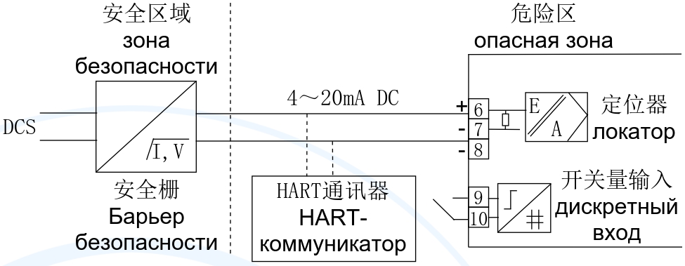 |
| Figure 4-8: Input Electrical Connection Diagram |
|
The HART handheld communicators provided on-site must be inspected and approved by a nationally recognized certification body for explosion-proof electrical products and must have obtained an explosion-proof certification. |
|
| Electrical Connections for the Valve Position Feedback Module (as shown in Figure 4-10) |
| Feedback Signal Type: |
Two-wire system, 4–20 mA DC |
| Temperature Drift: |
≤100 ppm/°C |
| Scope of Work: |
Operating Range: 3.6–20.5 mA DC |
| Accuracy: |
≤0.11 TP3T |
| Port Voltage: |
12–28 V DC |
| Intrinsic Safety Parameters (11+ to 12-): |
Ui = 28 V DC |
| Ii = 93 mA |
| Pi = 0.65 W |
| Ci = 10 nF |
| Li ≈ O |
| Safety Barrier Requirements: |
Uo ≤ 28 V DC |
| Io ≤ 93 mA |
| Po ≤ 0.65 W |
|
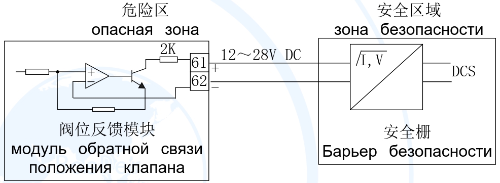 |
| Figure 4-10: Electrical Connection Diagram for the Valve Position Feedback Module |
| Connection of Non-Intrinsically Safe Positioners |
| Input Electrical Connections (as shown in Figure 4-11) |
| Type: |
Two-wire system |
| Input Signal: |
4–20 mA DC |
| Minimum operating current: |
3.8 mA DC |
| Input Impedance: |
325 Ω, 20 mA (without HART) |
| 375 Ω, 20 mA (HART type) |
|
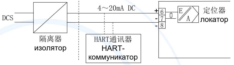 |
| Figure 4-11: Input Electrical Connection Diagram |

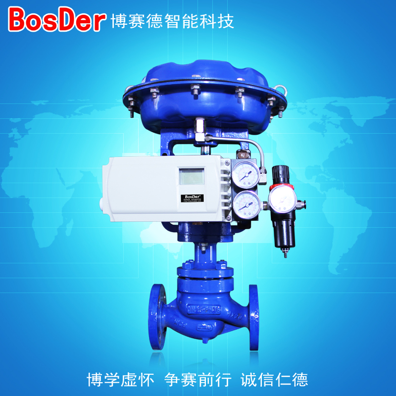
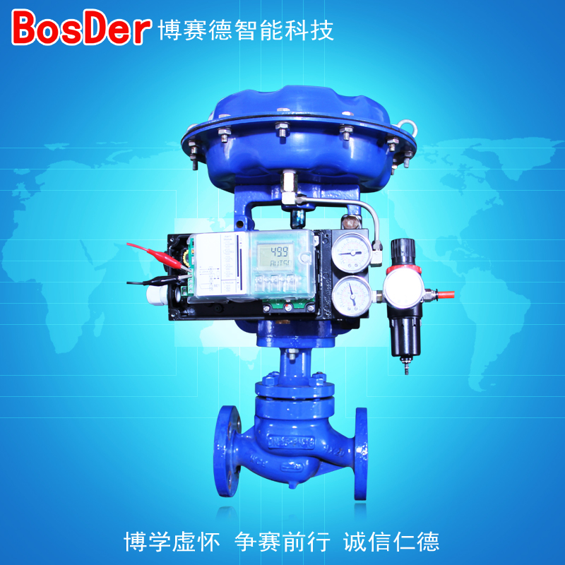
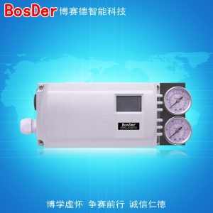
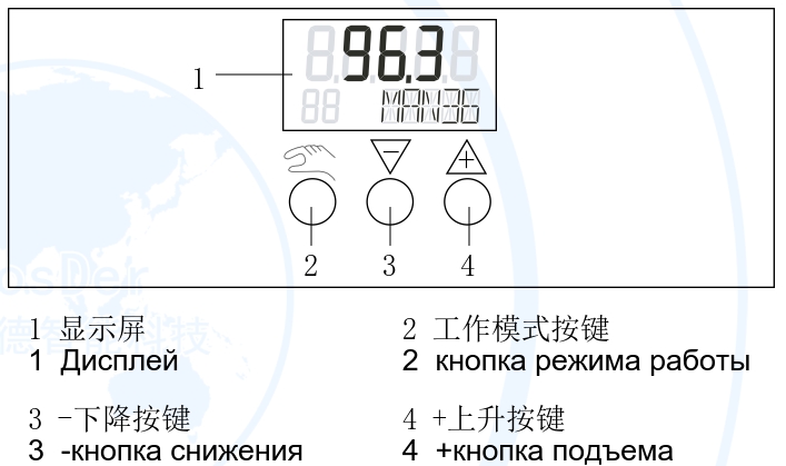
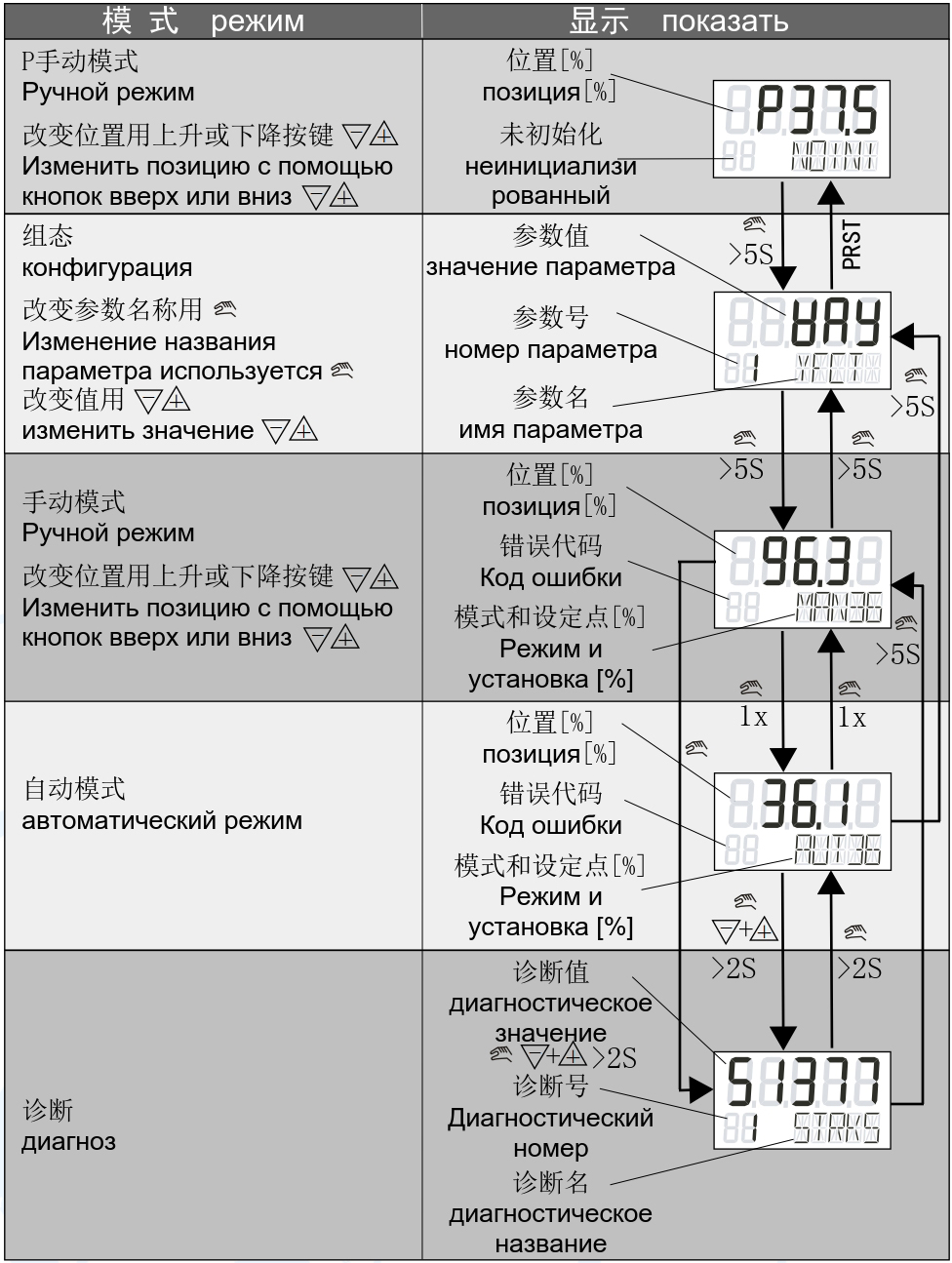
 If the user needs to change the positioner's parameter settings (normally, the user does not need to change the parameters, as the positioner meets the control requirements), press the button after the positioner is powered on.
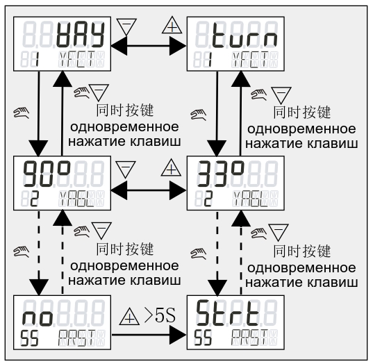
 Press and hold the button for more than 5 seconds to enter the parameter configuration mode. The user should select parameters based on on-site requirements (see the parameter configuration table for detailed settings). After completing parameter configuration, press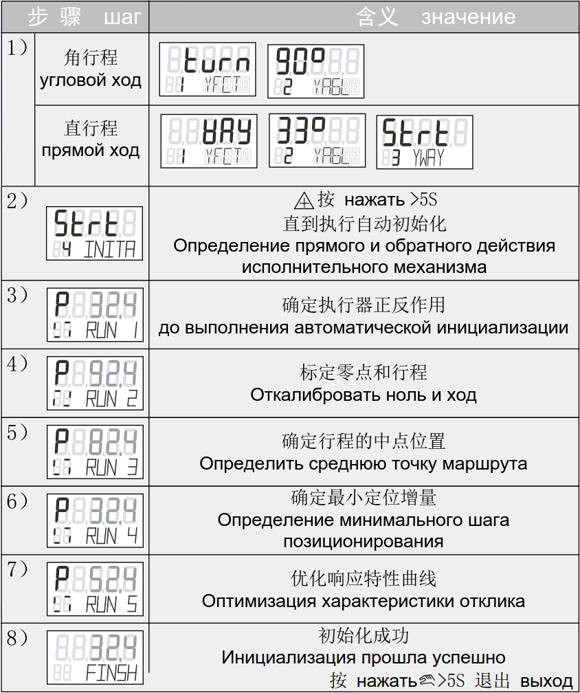


 If the key is held down (>5 seconds), automatic initialization begins. The initialization process displays “RUN1” through “RUN5”; when the “FINSH” symbol appears, continue pressing
 Key (>5 seconds)
 Key: Drive the valve to the fully closed position;
 Standard Valve Positioner Series
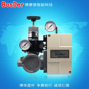 Standard Valve Positioner Series
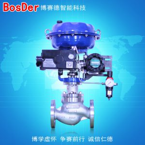 Automatic Control Valves